Kaiten Speaker

Originally designed as a Christmas present for my parents, these speakers took several iterations until I decided to finally post them online a full year later. The request was for speakers that can act as a surround sound system with our tv. This meant I would need bluetooth embedded in the electronics. Being new to audio systems, I was originally going to repurpose the speaker from the “Visualizing Sound” project, but decided against it in favor of a refreshed design. The speakers are intended to sit right behind the couch in our living room on two different windowsills. Given little room to work with, the speakers would need to be easily positioned and oriented for sound to travel throughout the room. I settled on the design you see above, being able to pan 360 degrees and tilt close to 90 degrees. This freedom of motion is what gave the Kaiten speaker its name; kaiten or 回転 means to turn or revolve in Japanese.
Below, I will go over how the most recent version is made, but also the older versions in lesser detail. The main difference between the old and new are the bluetooth modules and amplifier boards.
Speaker Parts

Note: Below are pictures of the speakers with older electronics components. Ignore the parts you see inside the speaker and follow the electronics section for the parts I use currently.
Print out all of the pieces below (link)
- Speaker cover x2
- Speaker sphere case x2
- Sphere holder x2
- Bearing base top
- Electronics base
- Base
- Bottom cover
- Wire spool
- Pin x2
- Pin lock x2
- Volume Dial
- Electronics base
Speaker Assembly


- Take both speakers and solder 15 cm (6 inches) of wire to each of the terminals (pictured: + yellow, - green). I used four M2.5 screws to fasten the speakers to each speaker's cover.
- Pass the pin lock through the wire first, then the pin next. Both facing away from the speaker as pictured.
- Fit the pin in the speaker sphere case as shown. Make sure to leave some slack for the wire. Then fit the pin lock against the pin. You can glue the pin lock to the pin in this step to make them permanent, however, it is not required.
- Screw the cover onto the sphere case.
- Pass the wires through the sphere holder first, then push the pin through.
- Take the bearing base and place a 608 bearing inside (get them from a fidget spinner). Screw the bearing base top onto the electronics base.
- Pass the wires through the bearing first, then push the pin through.
- Repeat with the other side, but make sure to use a far longer piece of wire depending on how you plan to space the speaker.
- Once you pull the wire through the bearing, attach the wire spool and fix it in place with hot glue if necessary.
- Pass the long wire through the hole in the side of the spool and wrap around. Then pass the wire through the small hole on the side of the base and into the small hole on the side of the electronics base.
Electronic Parts
The newest design combines the cheapest, smallest, and most versatile components that has plenty of customizability options. I have listed links for both eBay and Amazon. Just remember eBay will usually be cheaper at the cost of long delivery time and Amazon charges excessively for niche electronics.
- Speakers x2
- Audio amplifier
- Dual volume control potentiometer (optional)
- 12v female connector
- Audio jack (optional)
- Bluetooth module
- DC Buck Converter (powering the bluetooth module)
Electronics Assembly


Follow the circuit diagram to solder all of the parts together. If you don’t need bluetooth, then omit the buck converter and bluetooth module. If you have a modern iPhone, toss out the female audio jack. If you want both, like me, then follow the diagram. Don’t worry about hot swapping between the jack and bluetooth since nothing will short. The worst that would happen is overlapping sound. The volume control potentiometer is useful for manual control over the sound, but isn’t necessary since volume can be controlled by your phone. One benefit to the volume potentiometer is the built in switch for turning off the speaker.
Before soldering the bluetooth module to the dc buck converter we need to adjust the voltage on the buck converter to 5 volts. First, connect wires from the 12v plug to the “in” pins of the buck converter. Use a voltmeter to measure the output voltage. Turn the little potentiometer on the board using a Phillips head screwdriver until the output drops to 5 volts. Now it's safe to connect the bluetooth module.
Older Versions


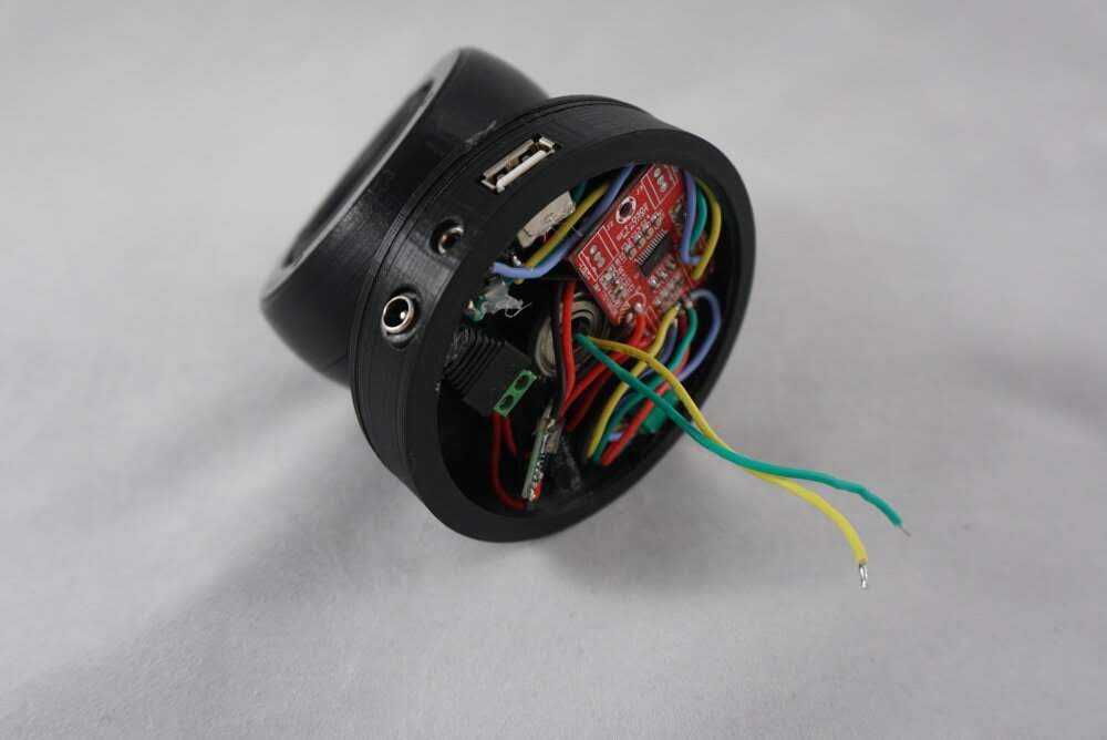
In my first design I tried using this amplifier which is excessive for the speakers I’m using. It has the added benefit of the volume dial integrated with the board. To make it fit with my design, you will have to desolder all components and extend each part with wires. Using this design I attached a buck converter to power a female usb connector. The idea here is to power an external bluetooth stick, often used for integrating bluetooth with cars, or a google chrome cast audio. A lot of parts dangle outside of the speaker which looked messy, so I moved onto the next idea.

This module is an all in one bluetooth, audio jack, and amplifier board. It’s relatively cheap and requires very little soldering; just the speakers and 12v female connector. The only thing I couldn’t get past was the built in voice prompt which spoke in broken English. If possible I would’ve liked a way to turn off the voice prompt, but there doesn’t seem to be a way...
So eventually I found the nice and cheap, bluetooth 4.2 capable, kcx-bt002 module. You can deactivate the voice prompt, remove the pins for unnecessary connections or expand on previously made designs. I can imagine the volume control and pause/play buttons being useful for a pair of headphones.